Chapter 6 - Graphical user interface
VI. Graphical user interface
GUIs (also known as graphical user interfaces) provide point-and-click control of software applications, eliminating the need for the user to learn the structure of the MATLAB program and to type commands in order to run the application. MATLAB offers three types of GUI building methods, the newest, App Designer, GUIDE (GUI development environment) and creating a GUI programmatically. This also features a rich environment for user to share their GUIs in the central webpage hub. To paraphrase the MATLAB webpage regarding App Designer:
App Designer is an environment for building MATLAB apps. It integrates the two primary tasks of app building―laying out the visual components and programming app behaviour―and allows you to quickly move between visual design in the canvas and code development in an integrated version of the MATLAB Editor.
And regarding GUIDE:
GUIDE (GUI development environment) provides tools to design user interfaces for custom apps. Using the GUIDE Layout Editor, you can graphically design your UI. GUIDE then automatically generates the MATLAB code for constructing the UI, which you can modify to program the behaviour of your app.
Our choice was mainly influenced by the abilities and the ease of use of App Designer introduced in version R2016a. MATLAB contains a fully integrated version of MATLAB editor. Layout and code views are tightly linked so that changes you make in one view immediately affects what you see in the other. Also, a large set of interactive controls are available. Most 2D and 3D plots are supported.
Although App Designer provides many of the same controls as GUIDE, the process for building apps is different, such as graphics support, generated code, component access, callback coding and plotting components. Differences are summarized in this table.
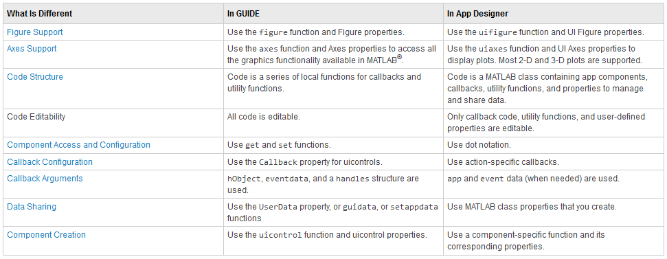
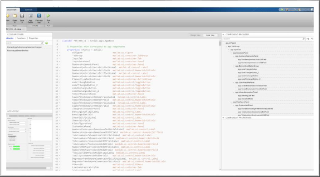
The code structure of App Designer is based on the MATLAB class structure, which is easy to read. App properties are shown first, then used-defined functions, and finally the code used for app initialization and component creation.
App code is edited using an integrated version of MATLAB Editor, integrated editor includes features such as smart indenting, Code Analyzer indicators and debugging.
To prevent the user from accidentally overwriting code that App Designer manages, some code is not editable, indicated by the light gray background. Callback code, helper functions, and property declarations that the user creates remain editable.
One user-friendly feature of App Designer is that it only creates callback declarations when the user explicitly requests it. This convention prevents empty callback declarations from cluttering the code. When the user triggers the callback by manipulating the component in the running app, the sample code accesses a component property value. The sample code provides an example of how to access a component and its properties within a callback. The user can replace this code with code that is appropriate for the app.
When saving the GUI only one MLAPP file is created that contains the information required to run the app. No associated FIG file is needed.
Components are defined as properties of the app. Components and their property values can be accessed using dot notation.
Components that support callbacks provide a ValueChangedFcn callback. All callback definitions specify app and event as input arguments. The app argument refers to app object, and all user interface components are defined and accessed as properties of this object. The event argument is an object that contains a reference to the UI component and specific information about the event.
To share data across callbacks, you create and use a property. Using properties is the best way to share data within an app because properties are accessible to all functions and callbacks in an app. All UI component are properties, so we can use this syntax to access and update components within the callback:
app.Component.Property
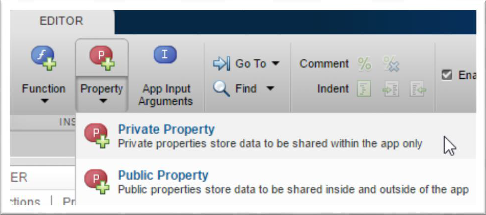
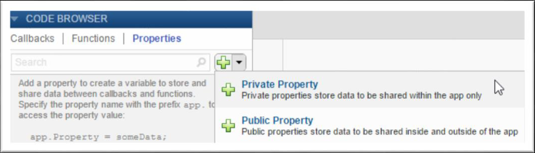
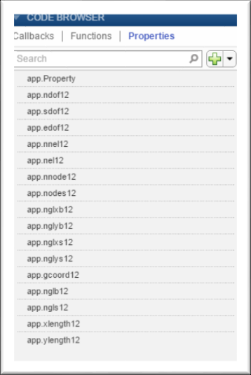
If we want to share an intermediate result, or data that more than one callback needs to access, then it is necessary to define a public or private property to store your data. Public properties are accessible both inside and outside of the app. Code view provides a few different ways to create a property.
Or using the Properties tab in the Code Browser.
App Designer code uses a different function for creating each type of component. Each component provides a set of properties designed specifically for that type of element.
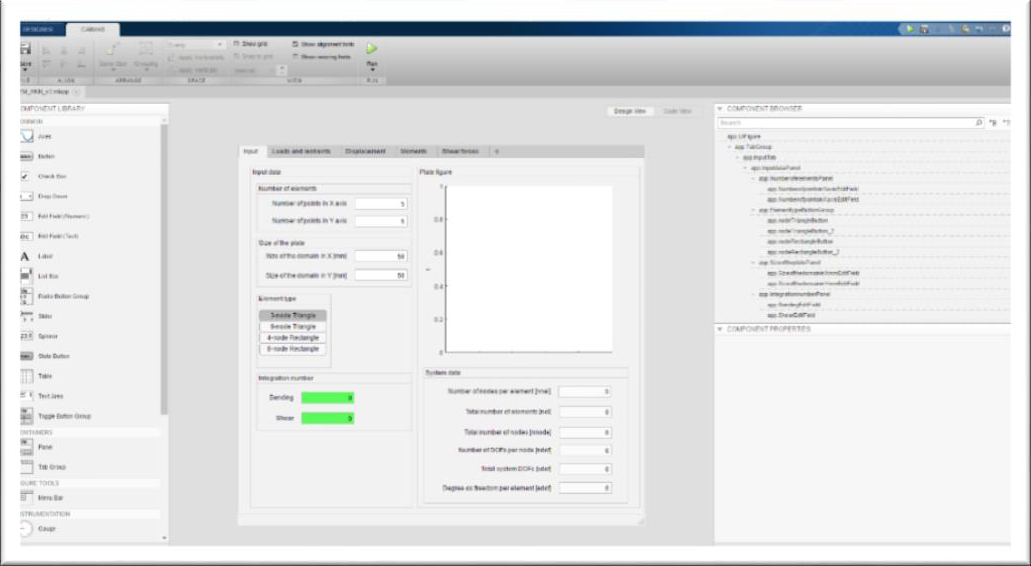
Components can be added in the Design View tab.
These two types of view options sum up the two main branches of App Designer. The visual part is built up in Design View with the help of components. This in our case means structuring the GUI under the terms dictated by the FEM steps.
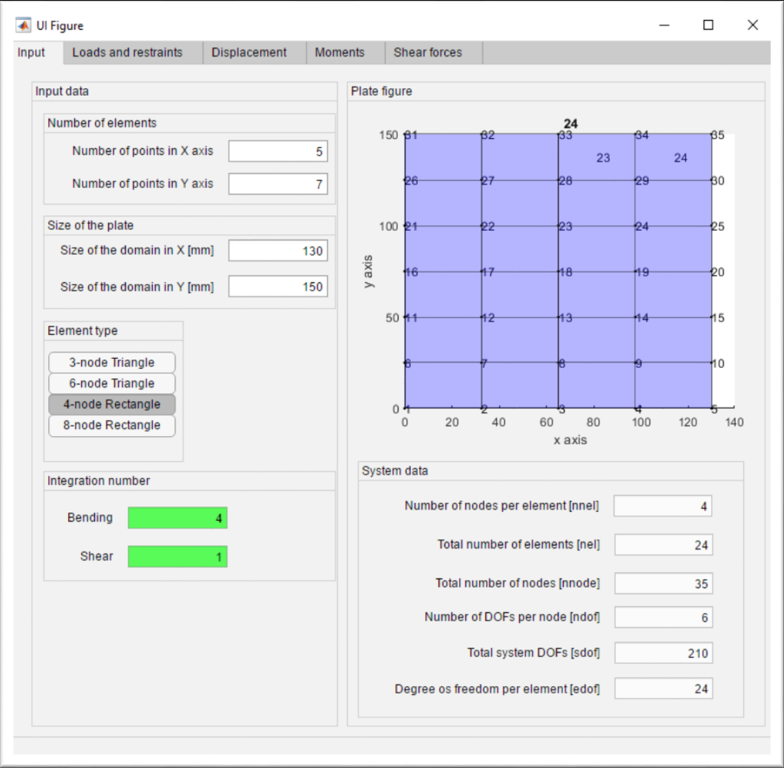
The GUI will have 5 tabs: Input, Loads and Restraints, Displacement, Moments, and Shear forces.
Input tab contains the components that are necessary to add input data to define the problem topology. For our current situation this means setting the number of points along $x$ axis and $y$ axis. Size of the domain along $x$ and $y$ axis.
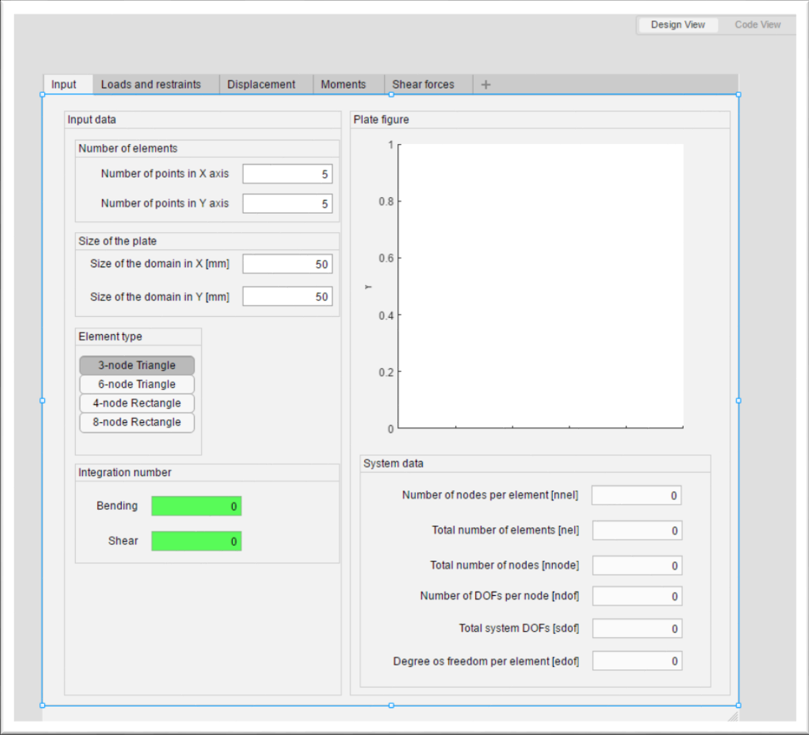
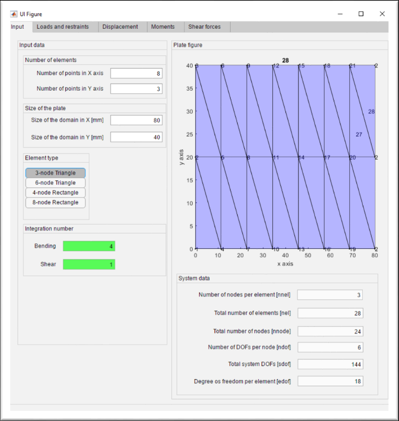
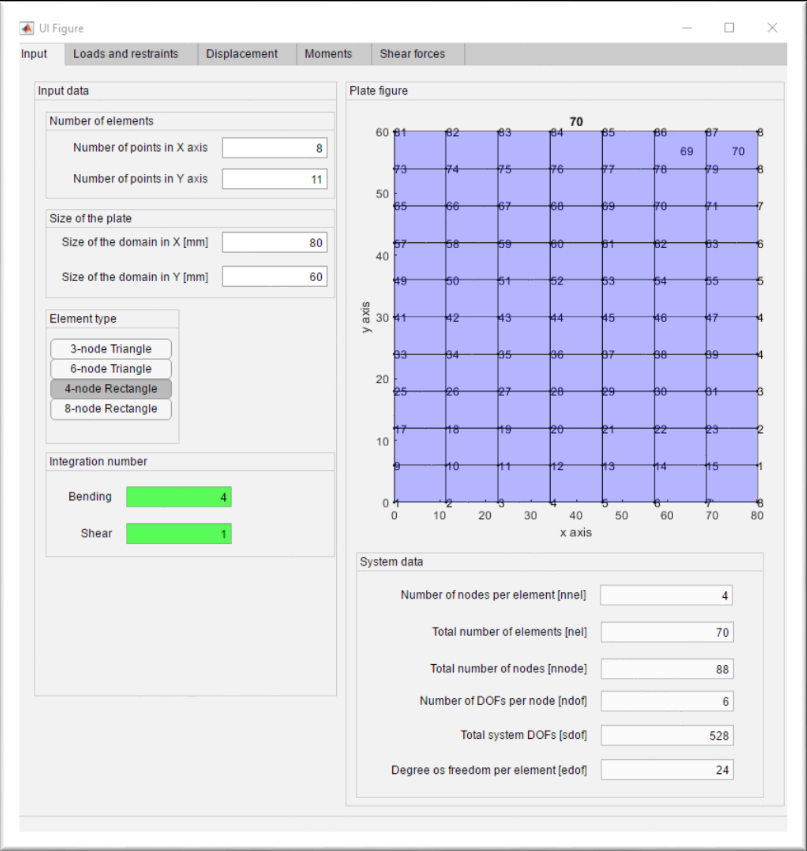
Element type can be selected according to the Toggle Button Group component. It gives the option to change between 3-node triangle, 6-node triangle, 4-node rectangle and 8-node rectangle.
The other elements present on this tab are the figure component to display element topology, integration number side tab (referring to the type of the integration) and system information regarding topology of the proposed problem.
In order to ensure the ability of each function to access data created in the input tab properties must be created. The method of creating and sharing properties were shown in figure 3 and 4.


Each type of element has its own switch case command to build up the necessary data regarding the system topology. This leads to the main idea behind a working GUI: issuing callbacks.
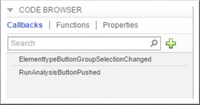
There are two callbacks for the GUI on this site:
ElementtypeButtonGroupSelectionChanged and RunAnalysisButtonPushed. While these long names may be cumbersome, but it actually makes sense to name a function or callback after what its purpose is, or what kind of action does it cause.
ElementtypeButtonGroupSelectionChanged as its name describes it calls
function ElementtypeButtonGroupSelectionChanged(app, event)
every time when a button selection is changed. This means that if we change the element type from default “3-node triangle” button to “8-node rectangle”, then the aforementioned function start running, changing the plot with the values assigned for choice “8-node triangle” and other input data.
Basically, all we have to do to see this callback being executed is to change the buttons responsible for element type.
Before we go on to the second callback, it must be ensured data is being shared inside the app. This done in the same manner as defining global variables, the only difference is that now it is called inside properties.
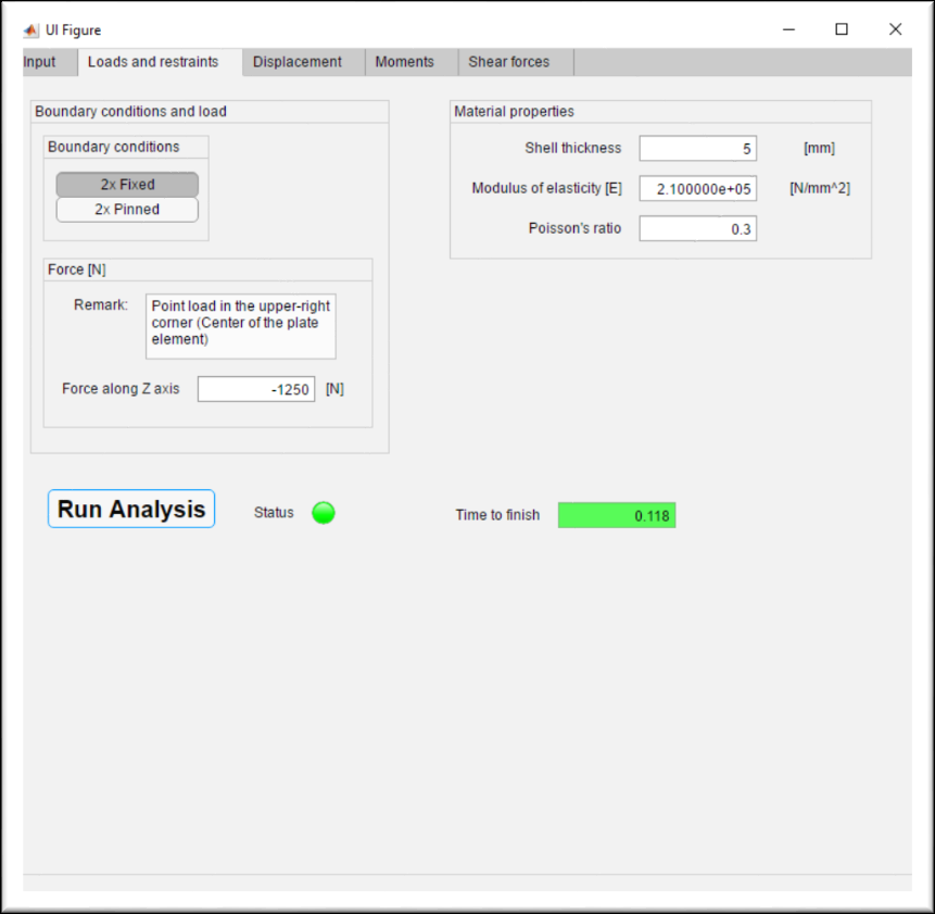
The second callback is called RunAnalysisButtonPushed. It is a function that is associated to “Run Analysis” button the can be found on the second tab “Loads and restraints”. Pushing the button calls
function RunAnalysisButtonPushed(app, event)
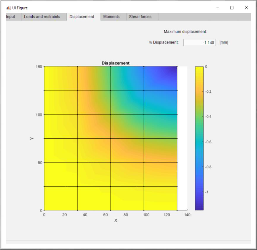
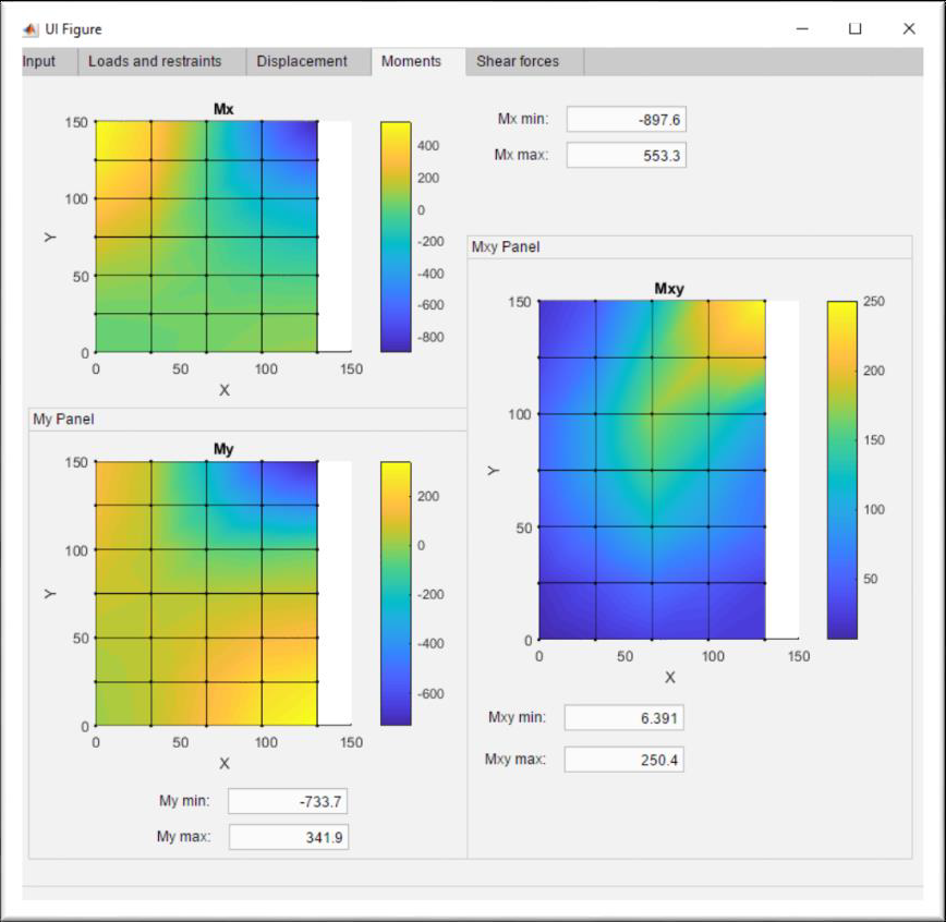
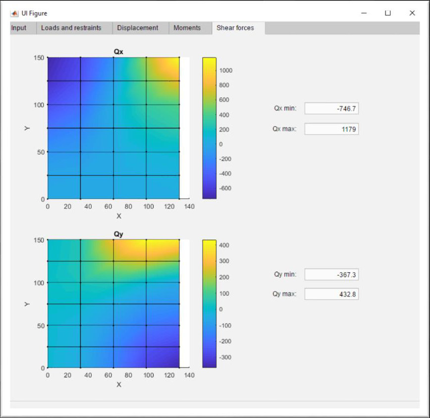
a function that after unloading the properties from the previous callback function, ElementtypeButtonGroupSelectionChanged, reads the input data from the second tab and runs the analysis of a quadrant of either a clamped or a simply supported plate loaded by a point load in its center (in the topology shown, it means the top right corner of the figure). Results on the next three tabs (Displacement, Moments, Shear forces). This function contains the linear solver framework presented in Chapter IV.
For example:
A plate having the size in $𝑥 = 130𝑚𝑚$ and in $𝑦 = 150𝑚𝑚$. With 4-node elements as in the figure, and a point load in the center with a value of 1250; fixed boundary conditions.
Complete FEM app with an user-friendly GUI can be assembled with the help of App Designer as shown in the following figures.